Sensor Thermistor Replacement Repair
Once the location of the sensor(s) has been determined, carefully remove the tile over the heat wire and proceed with the thermistor replacement as shown below.


Please contact our customer service team if you need assistance locating sensors. They will create a case and reach out to the area field technical manager.
csrusa@schluter.com
888-472-4588 ext 2
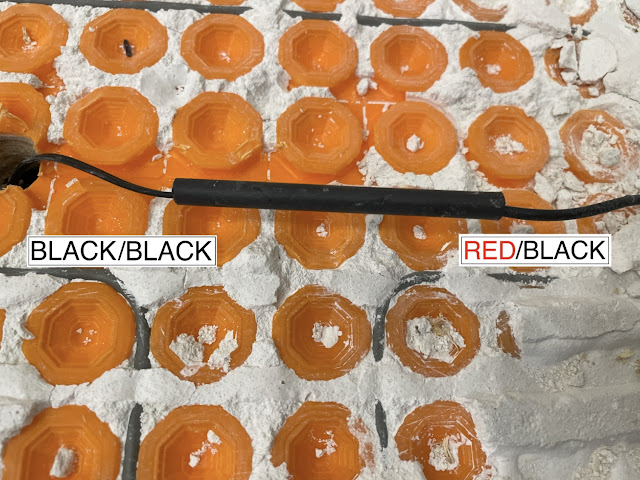
PHOTO 1 and PHOTO 2
- Cut off at least 6” from the thermistor end of the replacement Black/Black sensor wire.
- Cut off at least 6” of the end of the installed Red/Black sensor wire.
- NOTE: Photo 1 shows a method of repositioning a sensor wire to the middle of three puck spaced heat wire. This should carefully be done with a paddle bit and is only an option over a wood subfloor. Do not run sensor wires over the top or underneath of heat wires.


PHOTO 3
- Black/Black sensor - separate the lead wires from each other approximately 1”.
- Red/Black sensor - carefully remove approximately 1” of the outside insulation from the Red/Black leads.
- Carefully use wire strippers to remove 1/4” of the insulation from around each of the four leads.

PHOTO 4
- Use two of the small solder/shrink connectors from the Schluter wire repair kit. Insert one lead into each end of the connector so that the exposed wires overlap in the middle of the solder bead.
- Use an industrial heat gun to shrink the connector around the leads. Continue heating until the bead of solder melts and disperses around the leads.
- TIP: Use a damp rag to quickly cool the solder connection.

PHOTO 5 and PHOTO 6
- Slide a pre-measured and cut piece of the 1/4” black shrink tube over the top of the cooled spice.
- Use the industrial heat gun to shrink the black 1/4” tube over the splice. Begin in the middle and work towards each end respectively. Continue to move the gun and heat until you see glue come out each end.
- ⚠️ Be careful not to overheat and damage the insulation of the sensor wires.
- Cool the black shrink with the damp rag.


PHOTO 7 and CHART
- Snap the new known good Black/Black thermistor into the middle of a three puck run as shown below.
- Depending on the thickness of the weld, you may need to carefully cut away some of the membrane for the sensor to lay flat.
- From the junction box, find the leads of the sensor and do a kOhm test. Verify that the numbers yielded from the test coincide with the temperatures found in the range from the chart below. A successful test means a successful repair. The sensor can be connected to port C and D.


